DOEBRITZ ROTARY VALVE DIMENSIONAL DRAWING – OFFICIAL TECHNICAL OVERVIEW & DATASHEET
EXECUTIVE SUMMARY
This document serves as the definitive engineering reference for the Doebritz Rotary Valve Dimensional Drawing series. It provides comprehensive technical specifications, critical clearance data, and mounting interface details essential for plant engineers, system integrators, and procurement specialists. The Doebritz rotary valve is engineered for precision volumetric feeding, airlock sealing, and heavy-duty pneumatic conveying across diverse industrial sectors. This datasheet consolidates over four decades of German engineering excellence, focusing on the dimensional accuracy and interchangeability that define our OEM solutions.

HOUSING & ROTOR METALLURGY
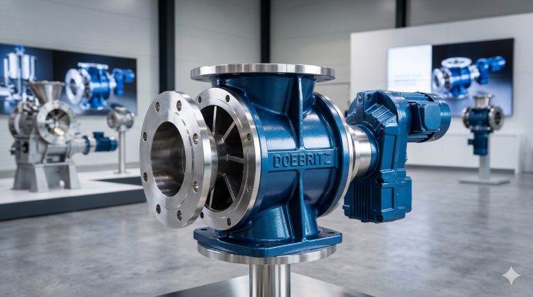
The foundation of the Doebritz rotary valve is its robust housing, precision-cast from high-grade ductile iron (GGG-40.3) or fabricated from stainless steel (316L / 1.4408) for corrosive or sanitary applications. The dimensional drawing specifies a housing wall thickness of 15mm minimum, ensuring structural integrity under differential pressures up to 3.5 bar (50 psi). The rotor, featuring 6, 8, or 10 vanes, is CNC-machined to exacting tolerances from a single billet of wear-resistant material, with hard-facing options available for abrasive media. All critical mating surfaces, including the flange faces and bearing housings, are machined to a surface finish of Ra 1.6 µm (63 µ-in) to guarantee leak-free operation and optimal seal life.
KEY FEATURES
– Precision-Ground Rotor-to-Housing Clearances: Standard radial clearance of 0.10 – 0.15 mm (0.004 – 0.006 in) ensures maximum volumetric efficiency and minimal air leakage. Custom clearances (0.05 – 0.30 mm) available per ATEX or NFPA requirements.
– Heavy-Duty Outboard Bearing Configuration: Bearings are isolated from the product zone with labyrinth seals and a pressurized air-purge system, extending operational life by up to 300% in abrasive applications.
– Modular Flange and Drive Interfaces: Dimensional drawings conform to DIN PN10/PN16 and ANSI 150#/300# flange standards. Drive configurations include direct drive, chain drive, and variable frequency drive (VFD) mounts, all with standardized shaft dimensions as per IEC or NEMA.
– Wear Defense Mechanisms: Standard hardfacing (Stellite or tungsten carbide) on rotor tips and housing liners. The dimensional drawing details replaceable wear plates and liners, facilitating maintenance without removing the valve body from the pipeline.
– High-Temperature Sealing Options: PTFE, Viton, or graphite-impregnated packing rings, with integral lantern ring for purging or lubrication.
COMPLIANCE & SAFETY STANDARDS
All Doebritz rotary valve dimensional drawings and manufactured units are certified to meet rigorous global standards. The engineering data is fully traceable and backed by a comprehensive quality management system (ISO 9001:2015).
– ATEX Directive 2014/34/EU: Standard offering for Gas and Dust atmospheres (II 1/2 G/D c T4/T6).
– NFPA 69 & NFPA 86: Standard for explosion prevention systems and ovens/furnaces.
– Pressure Equipment Directive (PED) 2014/68/EU: Category I to III depending on volume and pressure.
– ASME B31.3: Process Piping Code compliance for material and dimensional conformance.
– FDA / EC 1935/2004: Material compliance for food-contact applications (stainless steel variants).
TECHNICAL SPECIFICATIONS
The following parameters define the core operational envelope of the Doebritz rotary valve. The dimensional drawing provides the exact physical envelope for each model variant.
– Maximum Operating Pressure: 3.5 bar (50 psi) differential; up to 10 bar (145 psi) on request.
– Operating Temperature Range: -20°C to +250°C (-4°F to +482°F) depending on seal and material selection.
– Speed Range: 5 to 45 RPM; higher speeds available for specific dosing applications.
– Volumetric Efficiency: 85-95% depending on product characteristics and pressure differential.
| Parameter | Specification |
|---|---|
| Capacity / Volume | 2.5 to 100 Liters/rev |
| Flange Standard | DIN PN10 / ANSI 150# |
| Drive Configuration | Chain Drive / Direct Drive |
| Radial Clearance | 0.10 – 0.15 mm (standard) |
| Housing Material | Ductile Iron / 316L Stainless Steel |
| Rotor Material | Hardened Alloy Steel / 316L |
| Temperature Range | -20°C to +250°C (-4°F to +482°F) |
| Max Differential Pressure | 3.5 bar (50 psi) |
INDUSTRIAL DEPLOYMENT
The dimensional drawing is the cornerstone for integrating Doebritz valves into complete processing lines. Typical applications include:
– Pneumatic Conveying: As an airlock feeder for dense-phase and dilute-phase systems.
– Gravimetric and Volumetric Feeding: Precise, uniform discharge from hoppers, silos, and bins.
– Dust Collection and Venting: As a rotary airlock for continuous dust removal in baghouses.
– Chemical and Petrochemical Processing: Metering of powders, pellets, and granular solids.
– Food and Pharmaceutical Production: Sanitary design for handling ingredients and final products.
For system integration, the dimensional drawing specifies all critical envelope dimensions, including overall height, width, depth, flange locations, shaft centerlines, and mounting bolt patterns. This data is essential for preparing foundation layouts, connecting pipe spools, and aligning drive components.
MAINTENANCE & SERVICE STRATEGY
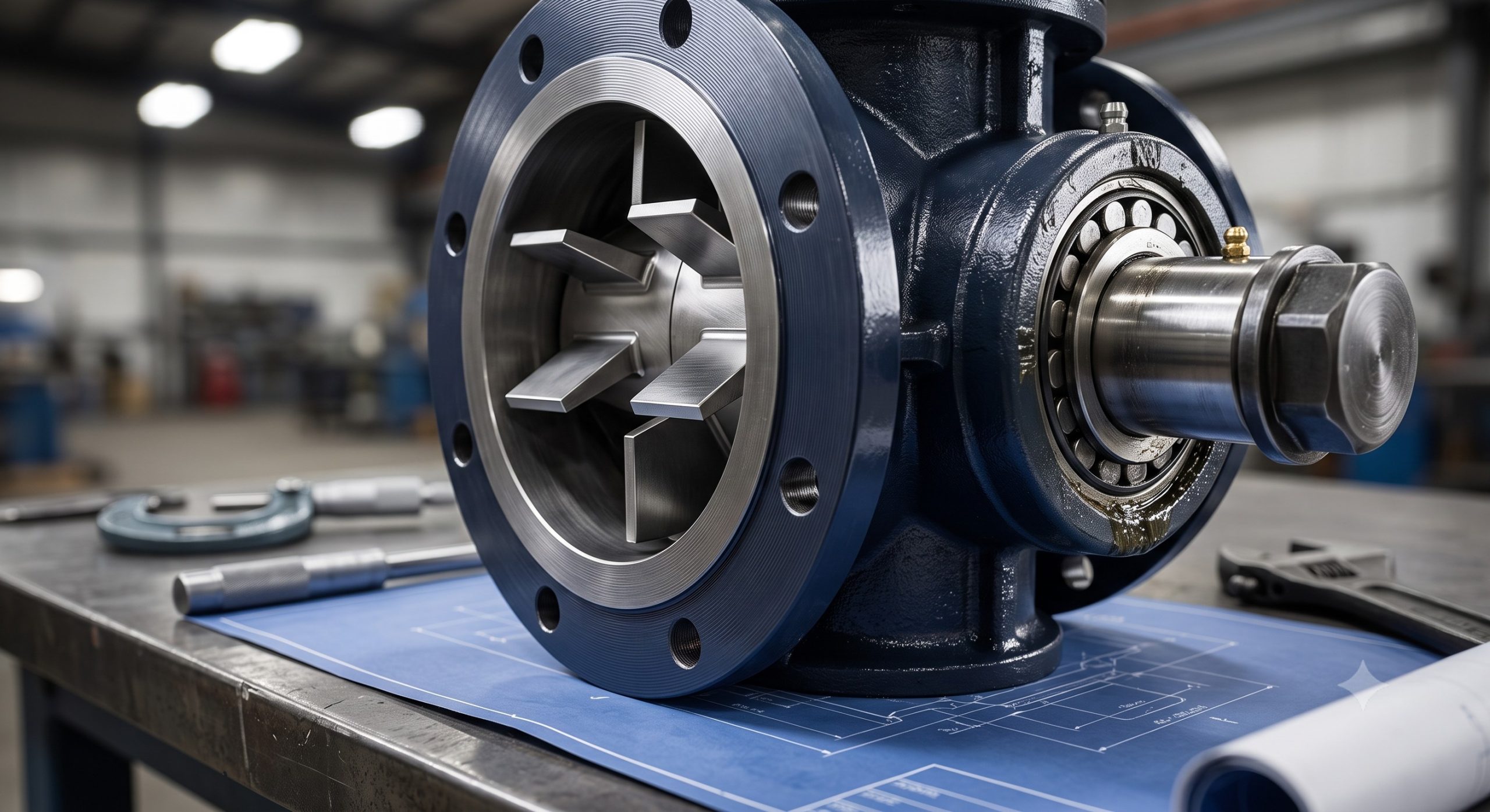
The Doebritz rotary valve is designed for condition-based maintenance. The dimensional drawing clearly identifies all serviceable points, including access for:
– Bearing lubrication and replacement.
– Shaft seal and packing ring renewal.
– Rotor tip clearance verification and adjustment.
– Inspection of housing liner and endplate wear.
The modular design, as reflected in the dimensional architecture, allows for in-situ repair of many components, minimizing plant downtime and reducing total cost of ownership. Doebritz provides complete repair kits and spare part drawings to ensure continued high-performance operation throughout the equipment lifecycle.
📥 Download Technical Specification
Click the button below to view or download the full official PDF datasheet.